Export FDS geometries
This page explains how the geometries referenced by a Blender Object are exported to FDS geometric namelists.
Table of contents
The Blender Object and its shape
Each Blender Object represents a geometric entity in the Blender Scene domain.
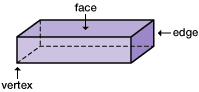
While the object data-block acts as a local reference system and contains the item location, rotation, and scale, the object shape is described by a related Blender Mesh data-block. The mesh is a collection of connected vertices, edges, and faces.
See the FIXME wiki page for a description of the Blender data-blocks and how they are exported/imported to the FDS case.
The traditional FDS geometric namelists
Some geometric FDS namelists extend their effects to volumes, planes, faces, segments, or points in the FDS domain. For example, this namelist generates a box-shaped obstacle to the fluid:
&OBST ID='Example obstacle' XB=-1.0,1.0,-1.0,1.0,-1.0,1.0, /
See the FDS User’s Guide for further details.
The more common geometric FDS namelists are: DEVC, HOLE, HVAC, INIT, MESH, OBST, PROF, SLCF, VENT, and ZONE. Those namelists always require one or more of the following geometric parameters: XB, XYZ, or PB* (that is PBX, PBY, or PBZ).
BlenderFDS manages those geometric parameters, and takes care of exporting/importing them to FDS as shown in the following paragraphs.
The XB parameter
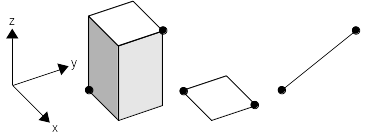
In FDS, the XB parameter is able to represent a parallelepiped parallel to the reference axis, a flat face perpendicular to one of the reference axis, or any segment in space. BlenderFDS proposes several different choices for exporting object shapes to the XB parameter.
XB | Exported as | Example |
|---|---|---|
BBox | One namelist, a parallelepiped corresponding to the bounding box of the shape |  |
Voxels | Many namelists, stair-stepping approximation of the shape volume | 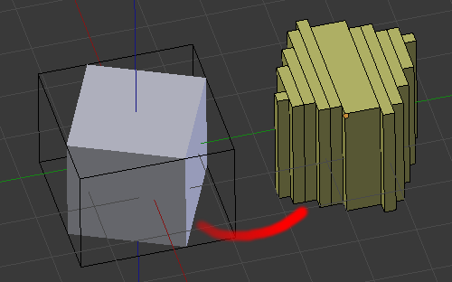 |
Faces | Many namelists, one per face of the shape, set parallel to reference planes | 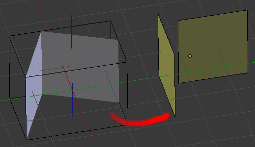 |
Edges | Many namelists, original shape edges. | 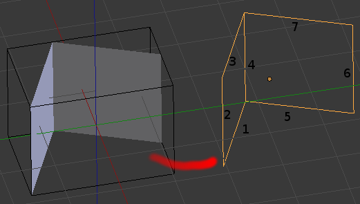 |
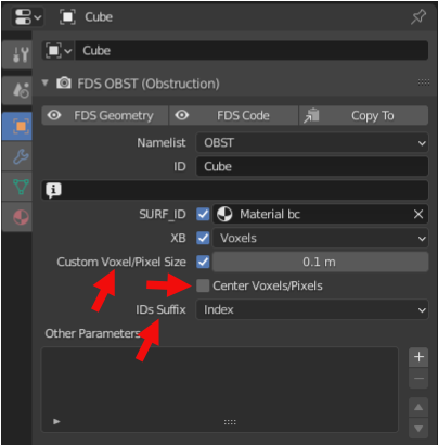
When stair-stepping the shape volume, the size of the voxel is taken from the Voxel/Pixel Size setting on the FDS Case Config panel.
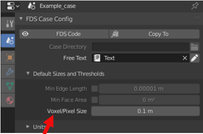
The resolution can be also customized for each object by filling the appropriate setting under the XB label.
The Center Voxels/Pixels setting centers the stair-stepping algorithm to the object, instead of the default alignment with other objects voxels. The default alignment prevents the formation of holes between the stair-stepped shapes. The voxel centering improves the fidelity of the stair-stepped geometry to the original shape, eg for creating a symmetric stair-stepped sphere.
The IDs suffix setting adds different kinds of suffixes to the object ID parameter, when generating multiple namelists from the same object.
The XYZ parameter
In FDS, the XB parameter is able to represent a point in space. BlenderFDS proposes two different choices for exporting object shapes to the XYZ parameter.
XYZ | Exported as | Example |
|---|---|---|
Vertices | Many namelists, one per shape vertex | 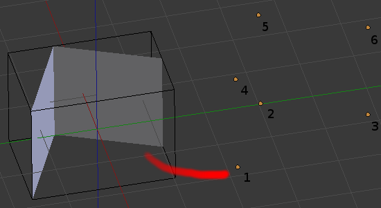 |
Center | One namelist, center point of the object | None |
For example, if you wish to create a line of thermocouples: add a new an object, set its namelist to DEVC and XB parameter to Vertices. Then create the vertices in the appropriate locations.
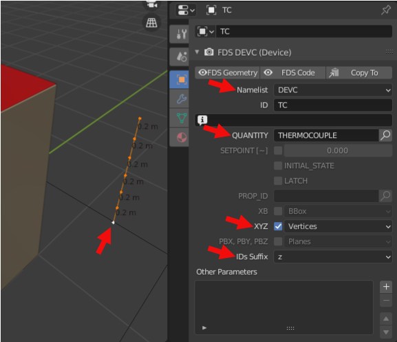
By setting the IDs Suffix to z you obtain these DEVC namelists with nice ID parameters:
! XYZ Vertices: 7
&DEVC ID='TC_z+0.500' XYZ=1.500000,1.500000,0.500000 QUANTITY='THERMOCOUPLE' /
&DEVC ID='TC_z+0.700' XYZ=1.500000,1.500000,0.700000 QUANTITY='THERMOCOUPLE' /
&DEVC ID='TC_z+0.900' XYZ=1.500000,1.500000,0.900000 QUANTITY='THERMOCOUPLE' /
The PBX, PBY, and PBZ parameters
In FDS, the PB* parameters are able to represent a plane perpendicular to one of the reference axis. BlenderFDS proposes one way of exporting object shapes to the PB* parameters.
PB* | Exported as | Example |
|---|---|---|
Planes | Many namelists, one per face of the shape, set parallel to reference planes | |
For example, if you need to generate several SLCF slice files: add a new an object, set its namelist to SLCF and PB* parameter to Planes. The faces you create in the object are transformed into planes, parallel to reference planes.
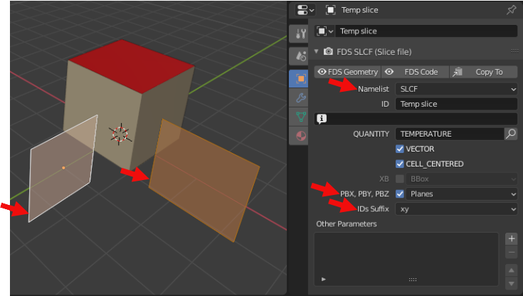
Here are the SLCF namelists you obtain:
! PB* Planes: 2
&SLCF ID='Temp slice_x+0.000' PBX=0.000000 QUANTITY='TEMPERATURE' VECTOR=T CELL_CENTERED=T /
&SLCF ID='Temp slice_y-0.000' PBY=-0.000000 QUANTITY='TEMPERATURE' VECTOR=T CELL_CENTERED=T /
The GEOM namelist
Recent FDS versions propose an additional geometric namelist named GEOM. This namelist extends the traditional OBST box-shaped obstacle to a generic-shaped obstacle in the fluid domain. The GEOM namelist requires other geometric parameters as VERTS, FACES, VOLUS, or the reference to an external .bingeom binary file called from the BINGEOM_FILE parameter.
For example:
&GEOM ID='Example' SURF_ID='S1','S2',...
      VERTS=-1.0,1.0,-1.0,... FACES=1,2,1,1,...
      /
&GEOM ID='Example' SURF_ID='S1','S2',...
      BINGEOM_FILE='~/example.bingeom'
      /
BlenderFDS can export/import both formats.
As already said, the shape of a Blender Object is made of vertices, edges, and faces. It is exactly the same representation used by the GEOM namelist in FDS. So the shapes of the objects can be exported/imported without modification.
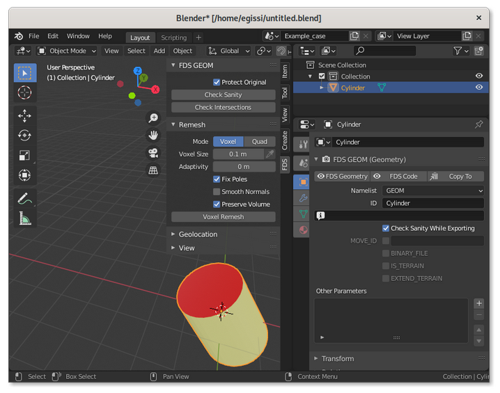
The GEOM properties panel
The GEOM properties panel has several settings.
FDS has strict requirements on the quality of the triangulated surface of GEOM namelists. When representing a solid obstacle in space, the surface shall be manifold and closed. So BlenderFDS performs a series of automatic sanity checks while exporting. If they are too intrusive for your use case, these checks can be disabled by toggling the Check Sanity While Exporting parameter.
If you want to add a MOVE namelist to explicitely write the rotation, location, and scale applied to the GEOM namelist shape, you can set the MOVE_ID toggle and also provide an optional name for the transformation.
If you want to export the binary format of the GEOM namelist, set the BINARY_FILE parameter. You can optionally select the path and filename of the .bingeom file that is going to be created upon export. The default filename is taken from the Blender Mesh name, that contains the shape of the object and can be shared between several object instances (eg. several identical chairs around a table, sharing the same Blender Mesh shape). If the same shape is shared by several GEOM instances, one only common .bingeom file is exported.
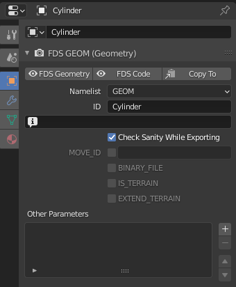
By setting the IS_TERRAIN toggle, the GEOM namelist can also be used to describe vast terrains, eg. for wildfire or smoke dispersion of fire pollutants simulations. In this case the GEOM namelist may only describe the surface of the terrain, there is no need to create the solid ground beneath it.
If the terrain geometry does not completely cover the calculation domain, set the EXTEND_TERRAIN toggle, and FDS will extend the surface to the entire domain.

Another companion tool for terrains is qgis2fds, an open QGIS plugin that exports terrains and landuse from geographical data for wildfire simulation and atmospheric dispersion of fire pollutants. The FDS file generated by qgis2fds can be imported to BlenderFDS for further customization.
The GEOM tool sidebar
The GEOM sidebar offers several tools for checking and fixing the triangulated surfaces, before exporting them to FDS.
When the 3D Viewport editor is in Object Mode:
-
if you click on the
Check Sanitybutton, the selected object triangulated surface is checked for manifoldness; -
clicking on the
Check Intersectionsbutton, you verify the existance of intersections between the current active object and all the selected objects geometries; -
if you untoggle the
Protect Originalsetting, when checking geometry sanity or intersections BlenderFDS selects the offending elements in the3D Viewportafter changing the editor mode toEdit Mode. Note that in this case the checked geometry has to be triangulated, thus modified from the original state.
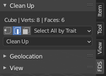
When the 3D Viewport editor is in Edit Mode, a Clean Up panel is shown, where selection tools and cleanup tools are offered.
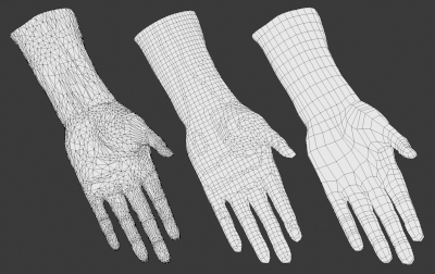
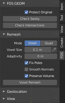
Remeshing panel
Remeshing is a technique that automatically rebuilds the geometry with a more uniform topology, and is often used to fix bad geometries by generating a new manifold mesh from the current geometry. It produces a mesh with perfectly even distributed topology.
The BlenderFDS Remesh panel is a convenience copy of the same panel used in Blender in Sculpting Mode. Read its documentation here.
See also the Blender Remesh Modifier for a different approach to the same technique, here is its documentation.